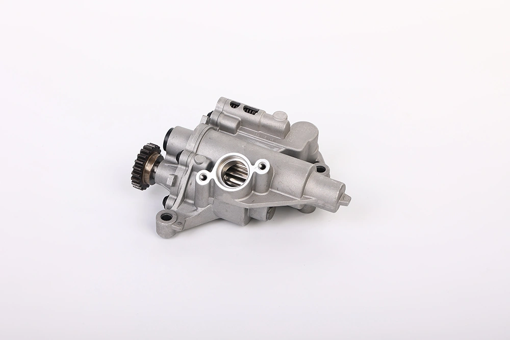
An EA888 engine can develop timing noise, oil-pressure warnings, turbocharger wear or contaminated engine oil without the oil pump being the only possible cause. The EA888 lubrication system connects the sump, oil pickup, pump, filter, cooler, oil galleries and several oil-fed engine components.
Understanding how these parts work together helps workshops avoid replacing one component while leaving a restriction, control fault or contamination problem elsewhere in the circuit.
The system layout varies between EA888 generations, engine codes and vehicle applications. Always use the repair information for the exact engine when checking oil specifications, pressure values, tightening procedures or component compatibility.
The lubrication system does more than send oil to the crankshaft bearings. It stores, draws, filters, cools, regulates and distributes engine oil before returning it to the sump.
Depending on the engine version, the system may include:
the oil sump;
an oil pickup and mesh screen;
a regulated oil pump;
an oil filter and filter housing;
an engine oil cooler;
pressure-control valves;
oil-pressure switches or sensors;
oil galleries in the cylinder block and cylinder head;
piston cooling jets;
turbocharger oil feed and return passages;
hydraulic timing-chain tensioners;
camshaft adjustment components;
oil return and crankcase separation passages.
Some components use oil mainly for lubrication. Others depend on controlled oil pressure for hydraulic operation.
This is why an oil-system problem may appear as a timing fault, start-up rattle, turbocharger issue or oil-pressure warning rather than as an obvious oil-pump failure.
The basic oil-flow path begins in the sump and ends when the oil drains back after lubricating and cooling the engine.
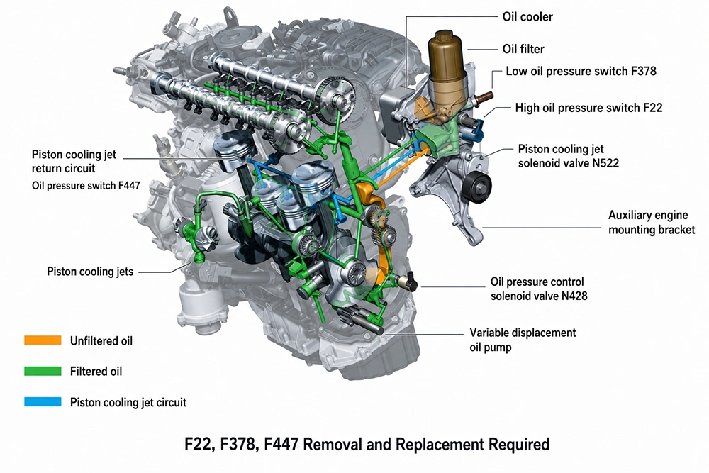
The oil pump draws oil through the pickup. A mesh screen helps prevent larger debris from entering the pump.
The pickup can become restricted by:
sludge;
hardened sealant;
damaged plastic or gasket material;
metallic debris;
heavy carbon deposits.
A restricted pickup can reduce the amount of oil reaching the pump even when the pump itself has no obvious external damage.
The EA888 family uses regulated oil-pump systems on relevant versions. Pump output changes according to engine operating requirements rather than remaining fixed under every condition.
The pump must receive a steady oil supply from the pickup. Its drive, internal clearances, regulation mechanism and connected control parts must also operate correctly.
Detailed pump construction and regulation should be covered on the existing EA888 oil-pump working-principle page. For system diagnosis, the more useful question is whether the pump receives oil correctly and whether the rest of the circuit can accept and distribute that flow.
The oil filter removes suspended contamination before the oil reaches sensitive engine parts.
The oil cooler helps manage oil temperature. Depending on the application, it may be integrated with the filter housing or fitted as part of a connected module.
Problems in this area may include:
an incorrect filter element;
a damaged or collapsed filter;
a missing internal insert;
blocked passages;
failed housing seals;
oil and coolant contamination;
incorrect assembly after previous repair work.
The filter housing and cooler should therefore be treated as part of the lubrication system rather than as unrelated service items.
Pressurised oil moves through galleries in the engine block and cylinder head.
These passages supply oil to areas including:
crankshaft bearings;
connecting-rod bearings;
camshaft bearings;
valve-train components;
timing-chain tensioners;
camshaft adjusters;
the turbocharger;
piston cooling jets on applicable engines.
A restriction in one passage may affect only part of the engine. This means a normal reading at one test point does not always prove that every component receives suitable oil flow.
After passing through the engine, oil drains back through return passages.
Restricted return flow can contribute to oil accumulation, aeration or unusual oil-level behaviour. During major engine repairs, both supply and return passages should be inspected where accessible.
Several engine components rely on clean oil delivered at the correct flow and pressure.
| Component | How it uses oil | What to inspect |
| Crankshaft and connecting-rod bearings | Maintains a protective oil film | Scoring, debris, wear and clearance |
| Camshaft bearings and valve train | Lubricates moving surfaces | Wear marks and restricted oil passages |
| Camshaft adjusters | Uses oil pressure to change valve timing | Oil condition, control valves and mechanical wear |
| Timing-chain tensioner | Uses hydraulic pressure to control the chain | Start-up noise, tensioner condition and oil supply |
| Turbocharger | Lubricates and cools the bearing assembly | Oil feed, return line, contamination and shaft condition |
| Piston cooling jets | Directs oil towards the piston underside | Blocked jets, control faults and gallery condition |
| Oil-pressure monitoring parts | Reports or helps control system operation | Wiring, connectors and mechanical pressure evidence |
A fault in an oil-fed component does not always mean the pump has failed.
For example, a worn camshaft adjuster may respond slowly even if pump output is acceptable. A blocked turbocharger feed line may damage the turbo while other engine parts still receive oil.
Replacing one visible part may not correct the cause of the fault.
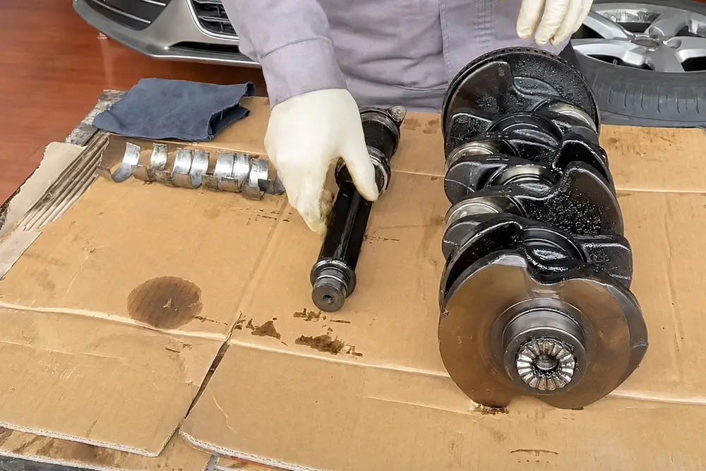
Metal particles from worn bearings, chains, gears or pump components can circulate through the engine.
Other contamination may include:
sealant fragments from previous repairs;
carbon deposits;
sludge;
coolant;
damaged plastic or gasket material.
If debris remains in the sump, pickup, filter housing or accessible galleries, it can damage a replacement component.
The workshop should record what type of contamination was found rather than describing the oil only as “dirty”. Useful evidence includes photographs of the sump and pickup screen, inspection of the opened filter element, separation of magnetic and non-magnetic debris, and notes on coolant or fuel contamination.
Camshaft adjusters and hydraulic chain tensioners depend on engine oil, but timing problems may also result from:
chain elongation;
guide wear;
a damaged tensioner;
incorrect mechanical timing;
control-solenoid faults;
wiring problems;
internal adjuster wear;
restricted oil passages.
A camshaft timing fault code does not identify the failed part by itself.
Oil-pressure switches, sensors and control valves may produce warnings or stored faults when there is a wiring, connector or signal problem.
The opposite is also possible. A normal electrical signal does not prove that every bearing and oil passage receives suitable lubrication.
Where a genuine pressure problem is suspected, the workshop may need both electrical checks and mechanical oil-pressure testing. The detailed testing process should remain on the existing EA888 low-oil-pressure diagnostic page.
EA888 is an engine family, not one fixed engine assembly.
Lubrication-system components may vary by:
engine generation;
engine code;
vehicle platform;
production date;
power output;
oil-pan configuration;
pump drive;
pressure-control arrangement;
oil-passage position;
connector type;
mounting points.
A component that looks similar may still have a different internal layout or operating specification.
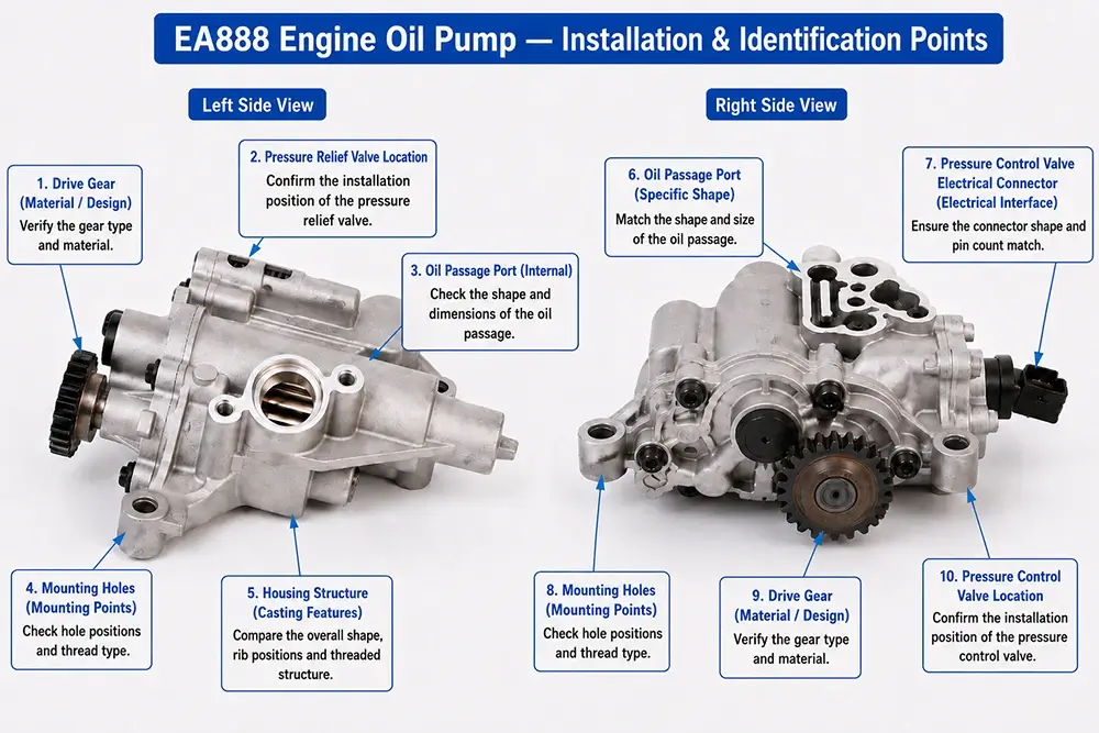
Before identifying a replacement part, record the complete engine code, vehicle identification number where available, production date, full OE number and suffix, casting references, connector details, mounting-face layout, oil-port positions and drive configuration.
Detailed Gen 1, Gen 2 and Gen 3 pump differences belong on the existing generation-comparison page. This article only explains why engine identification matters when inspecting the complete lubrication system.
The depth of inspection should match the symptoms and the repair being carried out. Routine servicing does not require dismantling the whole oil system.
Check for metallic particles, coolant, fuel smell, heavy sludge, unusually thick or thin oil, and plastic or sealant fragments.
The oil condition provides useful evidence, but it should not be used alone to identify a failed component.
Where lubrication damage is suspected, inspect the filter element for trapped debris.
Look for collapsed filter media, metallic particles between the pleats, sludge, coolant residue, damaged seals and incorrect filter construction.
Use a method that does not introduce additional metal fragments during inspection.
Inspect the oil-filter housing, oil-cooler connections, sump joints, timing-cover joints, turbocharger oil lines, pressure switches and recently disturbed sealing surfaces.
Avoid excessive sealant. Material squeezed inside the engine can detach and restrict the pickup or a small oil passage.
Record the oil specification used, oil viscosity, filter reference, service interval, previous timing or engine repairs, evidence of repeated oil top-ups and the amount of oil drained.
Use the oil specification listed for the exact vehicle and engine. EA888 applications cover many model years and markets, so one grade should not be presented as correct for every engine.
If the sump, cylinder head, timing system or turbocharger has been removed, inspect the accessible oil passages before reassembly.
Confirm that passages are clear, sealing material does not cover an oil port, the pickup and its seals are intact, filter and cooler connections are correctly assembled, and replacement components are lubricated or primed as required by the repair procedure.
Further diagnosis is justified when there is:
a red oil-pressure warning;
repeated pressure-related fault codes;
abnormal timing or bearing noise;
metallic debris in the filter or sump;
delayed timing-chain tensioner operation;
turbocharger damage linked to oil supply;
visible bearing wear;
an unexplained pressure-control fault.
Depending on the evidence, diagnosis may include scan-tool fault-code checks, live-data review, wiring and connector tests, mechanical oil-pressure measurement, oil-temperature confirmation, pickup and sump inspection, control-valve testing, mechanical timing checks, bearing-clearance inspection and oil-gallery examination.
Do not apply one general oil-pressure value to every EA888 engine. Pressure limits depend on engine code, oil temperature, engine speed and the specified test point.
A new component may fail again if the original cause remains in the system.
| Part being considered | Related items to inspect |
| Oil pump | Pickup, strainer, pump drive, regulation parts, sump contamination and bearing condition |
| Camshaft adjuster | Control solenoid, oil passage, camshaft, timing chain and tensioner |
| Timing-chain tensioner | Chain, guides, sprockets, oil supply and start-up noise history |
| Turbocharger | Oil feed, return line, filter, crankcase ventilation and contamination |
| Filter housing or oil cooler | Seals, internal valves, passage alignment and oil/coolant contamination |
| Pressure switch or control valve | Wiring, connector condition and mechanical pressure results |
Replacement is justified when testing or physical inspection identifies the component as damaged, restricted, worn or outside the relevant specification.
A warning light or fault code alone is not enough.
A parts supplier cannot verify an application accurately from “EA888 oil pump” or “2.0 TSI engine” alone.
Before requesting a quotation, record:
vehicle make and model;
VIN where available;
engine code;
production date;
engine displacement and output;
complete OE number and suffix;
photographs of the removed part;
connector configuration;
casting or stamped references;
reason for replacement;
related damage or contamination;
required quantity.
For regular B2B purchasing, also check cross-reference accuracy, consistency between supplied batches, clear application data, inspection and testing records, packaging protection, batch identification, and warranty and return procedure.
These checks reduce incorrect supply without turning a parts enquiry into remote engine diagnosis.
Before ordering an EA888 lubrication-system component, confirm:
the engine code;
the production date;
the complete OE reference;
any official superseded number;
mounting-hole positions;
oil-port layout;
connector type;
drive configuration;
included seals, valves or accessories;
the cause of contamination or wear;
related components inspected during the repair.
Do not approve fitment from appearance alone. Components with similar housings may have different oil channels, control arrangements or application limits.
It is the complete circuit that stores, draws, filters, cools, regulates and distributes engine oil. It includes the sump, pickup, oil pump, filter, cooler, galleries and oil-fed engine components.
No. Pump design, pressure control, oil passages, sump construction and related components vary by generation, engine code and vehicle application.
They include engine bearings, camshaft adjusters, hydraulic timing-chain tensioners, the turbocharger and piston cooling jets on applicable engines.
Yes. A restricted pickup can reduce the oil reaching the pump. The sump, pickup screen and contamination source should be inspected before replacing the pump.
No. Timing faults can result from chain wear, incorrect mechanical timing, camshaft-adjuster damage, control-solenoid faults or oil-supply problems.
Where low pressure is suspected, mechanical pressure testing is normally part of the diagnostic process. Use the specified method and values for the exact engine code.
Provide the engine code, VIN or production details, full OE number, connector configuration and clear photographs of the removed part.
Inspect the oil and filter, sump, pickup, accessible passages, related timing components, turbocharger oil lines, pressure-control parts and the source of any contamination.

 English