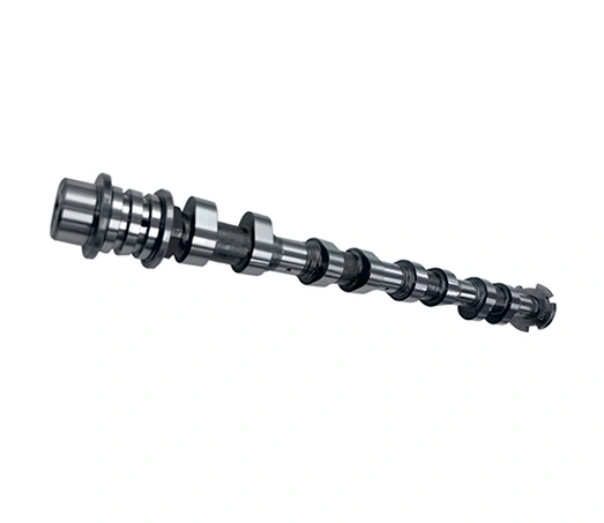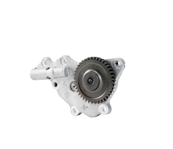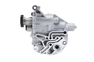
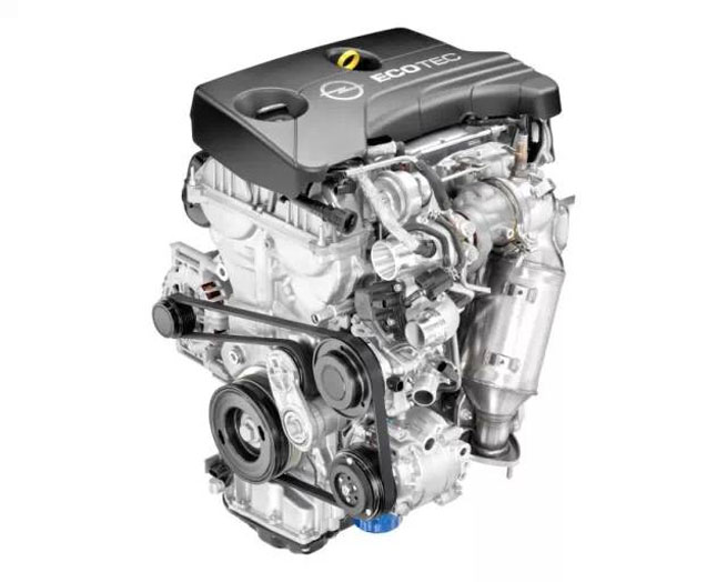
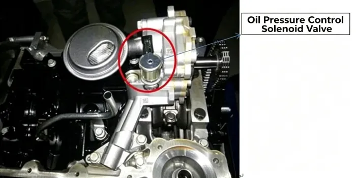
Figure 2 Electronically controlled variable displacement oil pump
An engine needs different oil flow and pressure at different temperatures, speeds and loads. A fixed-displacement pump is sized for demanding conditions, so at lighter load it may circulate more oil than the engine requires. Regulating displacement can reduce the power used to drive the pump while still supplying the lubrication system commanded for that operating condition.
A two-stage or continuously variable design changes pump output through a movable control ring or stator, hydraulic control chambers, a return spring and a control valve. The exact layout and default state vary by manufacturer; the operating description below must be matched to the pump being discussed.
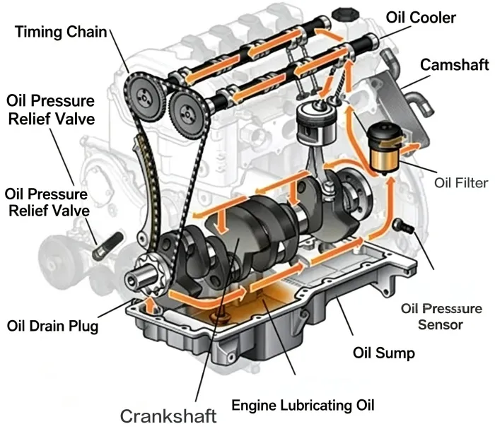
Figure 3 Principle diagram of engine lubrication system
In a vane-type pump, the space between the rotor and the surrounding control ring determines how much the pumping chambers expand and contract during one revolution. Greater eccentricity produces a larger change in chamber volume and therefore greater displacement. Moving the control ring closer to the rotor centre reduces eccentricity and displacement.
Hydraulic pressure acts on the control chambers to move the ring against a return spring. The control solenoid routes or vents oil according to the engine-control command. The balance between chamber pressure, spring force and pump outlet pressure determines whether the pump operates in a lower- or higher-displacement state.
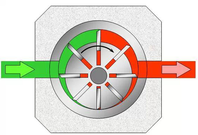
Figure 4 Basic working principle of vane oil pump
Operating state | Control objective | Mechanical position | What to observe during diagnosis |
Lower displacement/pressure stage | Reduce pump drive loss when permitted | Reduced rotor-to-ring eccentricity | Commanded stage, actual pressure, oil temperature and response time |
Higher displacement/pressure stage | Supply increased lubrication demand or protective operation | Increased eccentricity | Pressure rise after command, control-valve state and mechanical gauge result |
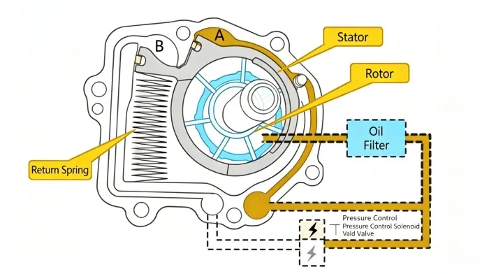
Figure 5 Large displacement state
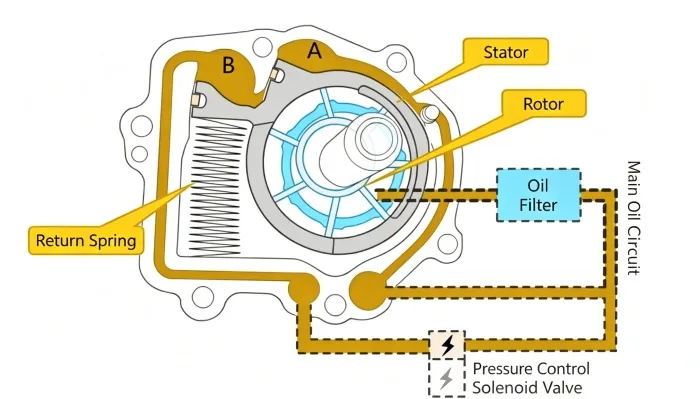
Figure 6 Small displacement state
The ECU may use engine speed, load, oil temperature, coolant temperature and other inputs to select the required pump state. Depending on the design, the solenoid may use on/off or pulse-width-modulated control. The ECU command changes hydraulic pressure in the control chambers, which moves the control ring and changes displacement.
Do not describe “powered” as universally equal to low displacement or “unpowered” as universally equal to high displacement. The electrical command and fail-safe position must be confirmed from the service information for the exact engine.
A circuit fault, sticking valve, restricted oil passage or mechanical pump problem may prevent the commanded pressure stage from being reached. Some systems are designed to move toward a protective state after an electrical failure, but that behaviour is not universal and does not guarantee correct lubrication.
Warning messages, pressure-related codes, an implausible pressure signal or a failure to switch stages should be diagnosed immediately. Actual pressure must be compared with the specification for the exact engine and oil temperature.
1. Confirm the engine code, specified oil, filter and oil level.
2. Save all pressure-control codes and freeze-frame data before clearing them.
3. Warm the oil to the test condition specified by the manufacturer.
4. Read commanded pressure stage, actual pressure and control-solenoid command.
5. Verify sensor data with a mechanical pressure gauge at the specified test point.
6. Command both stages where the diagnostic tool and procedure permit it.
7. Inspect the solenoid circuit, connector, oil passages, pickup and filter.
8. Consider internal engine leakage or excessive bearing clearance before condemning the pump.
9. Replace or repair components only as permitted by the exact workshop procedure.
Specification warning: Do not use 180 kPa, 85°C or any other pressure/temperature value as a universal specification. Publish a numeric threshold only when the engine, test point, oil temperature, RPM and source document are identified.
Compare this general explanation with the EA888 oil-pump structure and operation guide and the EA888 low-oil-pressure diagnostic guide. For replacement enquiries, use the automotive oil-pump category and provide the engine code and original OE number.

 English